Manufacturing and Testing
This section walks through the actual manufacturing processes and testing that was carried out in preparation of the actual pod. Images compare the actual manufactured part with the part as designed in the CAD software. Overall, it was a great experience to learn the different manufacturing methods and what challenges each method brings forward.
Chassis - Positive mold
This positive body mold was overlaid on with carbon fiber to create the outer shell of the pod. Manufacturing this was a tough job and involved quite a bit of precision and tolerance with the CNC machines and stacking of the mold. The body was cut into 1 inch thick slices vertically and the resulting profile of the pod was milled out on 8x4 plywood sheets.
The process steps were roughly -
- Subtract the CAD part from a block of 8x4 plywood cube
- Slice up the remaining plywood cube into the thickness of a plywood sheet
- Mill out the resulting profile of the pod's outer shape from the plywood sheets
- Mill out holes to act as datum for stacking the ply sheets on top of one another
- Stack the sheets on top of one another
- Sand out the external profile of the sheets to create a smooth surface
- Lay out the Carbon Fiber with the epoxy over this external surface

Subtract the Pod from a stack of plywood sheets

Image shows the milling simulation for a negative mold. The opposite was done for a positive mold.

Stacking the sheets and gluing them to get the positive mold
Subtract the Pod from a stack of plywood sheets
Carbon Fiber Molding
The resulting positive mold was sanded to get a smooth surface finish before beginning the carbon fiber molding process which was a week long process. The method was tried successfully on a quarter scale pod before proceeding with the full scale one. A decision was taking to mill out a positive mold instead of a negative mold to get to the correct tolerance after the sanding process. Restrictions on the size of the vacuum bag made us go with the positive mold, though milling a negative mold was easier.
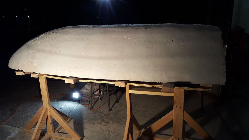
Front part of the sanded and stacked plysheets during the molding process

Close up of the front part before vacuum sealing

Rear part of the pod after being fitted on the chassis
Front part of the sanded and stacked plysheets during the molding process
Water Jet - Chassis and Sub Assemblies
These images show the chassis being built. The actual manufactured chassis can be seen with respect to the CAD design. Individual sub assemblies can be seen after being water jet cut and before and after the welding process.

A render of the Chassis

The Chassis after being manufactured - water jet cut and welded

The welded braking module
A render of the Chassis